A Regenerative Thermal Oxidizer (RTO) can turn a difficult emissions-control task into a practical heat-recovery opportunity. It captures heat from treated exhaust and reuses it to warm incoming process air. Picture hot air leaving a production line, passing through ceramic media, and transferring much of its heat before discharge. The result can be lower fuel demand than in a system without heat recovery. But performance depends on the exhaust stream, operating hours, and careful system design.
The U.S. Environmental Protection Agency’s Air Pollution Control Technology Fact Sheet for regenerative incinerators reports typical volatile organic compound (VOC) control efficiencies of 95–99%. The EPA’s Air Pollution Control Cost Manual also treats energy recovery and operating conditions as important factors in evaluating thermal oxidizers. These figures are useful benchmarks, not guarantees for every installation. Actual results require site-specific engineering and verified performance data.
Why choose an RTO? The answer may include strong VOC control, recovered process heat, and reliable operation across suitable applications. Still, ceramic beds, switching valves, pressure drop, and maintenance deserve close attention. One detail is easy to underestimate: a high quoted destruction efficiency does not, by itself, prove the lowest lifetime cost. For a credible expert quotation, a named source and verifiable publication are needed; without them, assigning a direct quote would risk misrepresenting the expert.
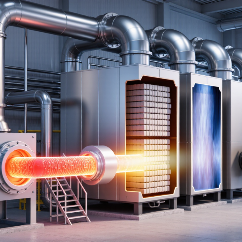
A regenerative thermal oxidizer, or RTO, controls certain industrial air emissions by heating contaminated process air until many organic compounds are oxidized. It typically uses a combustion chamber and ceramic heat-transfer beds. As hot, treated air leaves the chamber, the ceramics absorb heat. Valves then direct incoming air through warmed beds, recovering energy for the next cycle. Flow direction changes periodically, so the system can operate continuously.
An RTO may suit operations with steady exhaust flows and compounds that respond well to thermal oxidation. Actual performance depends on inlet temperature, flow rate, contaminant concentration, and equipment design. These details matter. A site assessment should review the process stream and operating patterns; an RTO is not automatically the right fit for every exhaust.
Tips: Track airflow and inlet temperature during representative production shifts. Check for dust, moisture, or changing contaminant loads, since these can affect bed condition and system stability. Keep careful operating records. They help reveal patterns, though real-world readings may not tell the whole story.
Why Choose a Regenerative Thermal Oxidizer?
How Does a Regenerative Thermal Oxidizer Work?
A regenerative thermal oxidizer, or RTO, cleans industrial exhaust through controlled oxidation. Fans move VOC-laden air into a ceramic heat-recovery chamber. A burner raises the gas temperature, usually between 760°C and 1,000°C. At this temperature, volatile organic compounds react with oxygen. They become mainly carbon dioxide and water vapor.
The ceramic beds then capture and release heat in alternating cycles. One bed absorbs hot, treated gas. The other preheats incoming exhaust. Valves reverse the airflow repeatedly. This design reduces burner demand and supports stable operation. The US EPA Air Pollution Control Cost Manual reports heat-recovery efficiencies that can approach 95%. Properly operated systems can also achieve VOC destruction efficiencies above 98%. Actual results depend on residence time, mixing, temperature, and pollutant chemistry.
Tips: Check airflow, pressure drop, and valve timing during routine inspections. Keep an eye on ceramic fouling. It can quietly reduce efficiency. A plant audit should compare inlet loading with outlet measurements, not rely on assumed figures. The European Environment Agency also emphasizes monitoring and operating control for thermal treatment systems. An RTO is powerful, but it is not a magic box. Poor maintenance, fluctuating exhaust, or incomplete commissioning can weaken performance. A design based only on brochure numbers is incomplete.
Why Choose a Regenerative Thermal Oxidizer?
Which Industrial Emissions Can It Treat?
A regenerative thermal oxidizer can treat exhaust streams containing volatile organic compounds (VOCs), which are released during processes such as coating, printing, and solvent use. It can also help control certain odorous compounds from food processing and chemical production. Inside the unit, high temperatures oxidize suitable pollutants, while ceramic media captures and reuses heat. The exact reduction depends on the compound, its concentration, and the system’s operating conditions. Not every exhaust stream behaves the same way.
Some compounds need careful evaluation. Halogenated or sulfur-containing pollutants may form corrosive by-products during oxidation, so a facility may need additional treatment equipment. An RTO is not a general-purpose filter for dust, metals, or acid gases. Those contaminants may require separate controls before or after the oxidizer. Sample the exhaust first. A clear understanding of flow rate, temperature, moisture, and pollutant mix helps engineers assess whether the technology fits. Real plant conditions can fluctuate, and that detail is easy to underestimate.
Which industrial emissions can it treat?
RTOs are commonly used to oxidize VOCs, many hazardous organic air pollutants, odorous organic compounds, and carbon monoxide. They do not generally remove particulate matter or inorganic gases such as sulfur dioxide, hydrogen chloride, and nitrogen oxides; separate controls may be needed. Actual suitability depends on the exhaust stream and system design.
Regenerative thermal oxidizers (RTOs) destroy many volatile organic compounds by heating contaminated process air. Ceramic media captures heat from treated exhaust and transfers it to incoming air, reducing the fuel needed to maintain operating temperature. For facilities with steady, high-volume exhaust, this heat recovery can lower energy costs and help manage emissions reliably. Properly selected equipment can also handle changing pollutant concentrations, though performance depends on the actual gas stream.
There are trade-offs. An RTO needs space, ductwork, controls, and regular inspection of valves and ceramic beds. Dust, sticky aerosols, or corrosive compounds may foul or damage internal components unless pretreatment is suitable. Startup and low-load operation can consume significant fuel, so a system may be less attractive for intermittent production. Fans also use electricity, and switching valves can create pressure fluctuations. That matters. Before choosing one, engineers should measure airflow, temperature, moisture, and contaminant composition across real operating shifts. A tidy design estimate can miss a messy production day. RTOs are not a universal fix; comparing their lifecycle costs with other treatment options can reveal whether heat recovery offsets installation and maintenance demands.
Choosing a regenerative thermal oxidizer starts with the exhaust, not a catalog. Measure airflow, temperature, and contaminant concentrations across normal production and peak periods. A system sized for an average day may struggle during a short, heavy load. Check whether the process stream changes with shifts, cleaning cycles, or product types. These details matter.
Compare destruction requirements, heat recovery, pressure drop, and available floor space. Ask how the unit handles startup, shutdown, and sudden changes in flow. Review expected fuel and electrical use under realistic operating conditions, not only ideal conditions. Request clear performance assumptions and a plan for verifying them after installation. A qualified process engineer can help assess these trade-offs. No spreadsheet captures every production surprise, and the assumptions deserve a second look.
Maintenance keeps performance dependable. Inspect ceramic media for fouling, damage, or uneven settling, and follow the manufacturer’s service intervals. Check valves, seals, burners, sensors, and fans; small leaks or sluggish valve movement can affect temperature and heat recovery. Keep records of operating temperatures, pressure drop, alarms, and fuel use. Trends can reveal trouble before an unexpected shutdown. Operators also need practical training, including what to do when readings drift. Even a well-designed system needs attention; that part is easy to underestimate.
| Decision or Maintenance Area | Typical Data or Consideration | Practical Guidance |
|---|---|---|
| Best-fit applications | Industrial exhaust containing volatile organic compounds (VOCs) or certain odorous air pollutants, often with moderate-to-high airflow. | Confirm that the pollutant mix is suitable for thermal oxidation and that exhaust contaminants will not damage equipment or create hazardous by-products. |
| Thermal oxidation temperature | Many RTO designs operate at approximately 760–870°C (1,400–1,600°F), depending on the compounds and required treatment performance. | Establish the required operating conditions through process-specific engineering and applicable permit requirements; temperature alone does not determine performance. |
| Residence time | A design residence time of around 0.5–1.0 second is common in many thermal oxidation applications, but requirements vary by pollutant and operating conditions. | Verify residence time at the specified temperature and actual gas flow, rather than relying on a general rule of thumb. |
| Heat-recovery efficiency | RTOs commonly use ceramic media to recover heat; thermal energy recovery is often designed in the approximate range of 90–97%. | Compare guaranteed performance at the expected flow, inlet temperature, and operating pattern. Higher heat recovery can reduce supplemental fuel demand. |
| Destruction efficiency | Well-designed systems may achieve VOC destruction efficiencies of 98% or higher for specified compounds and operating conditions. | Check the performance guarantee, test method, pollutants covered, and any required monitoring or reporting conditions. |
| Flow rate and operating schedule | System sizing depends on actual and peak exhaust flow, temperature, pollutant loading, and hours of operation. | Use representative process data, including production peaks and batch cycles. Oversizing or frequent low-load operation may affect energy use and stability. |
| Combustion safety | Flammable concentrations must remain within safe operating limits; the applicable limit and safety margin depend on the process and governing codes. | Assess worst-case concentrations and upset conditions. Specify suitable monitoring, interlocks, purge sequences, and safeguards with qualified engineers. |
| Pressure drop and fan capacity | Ceramic beds, ductwork, dampers, and particulate buildup contribute to system pressure drop. | Confirm available fan capacity and evaluate pressure-drop trends over time. A rising trend can indicate fouling, blocked media, or damper problems. |
| Weekly or routine checks | Review alarms, temperature readings, pressure readings, burner status, and visible signs of leakage or unusual noise. | Record readings consistently and investigate changes from the normal operating baseline before they become persistent faults. |
| Preventive maintenance | Inspect burners, valves, dampers, sensors, seals, and electrical or control components at intervals set by the equipment design and duty cycle. | Follow the operating manual and site maintenance plan. Calibrate instruments and test safety interlocks at the specified intervals. |
| Ceramic media condition | Media can become fouled, cracked, displaced, or plugged by dust, condensed material, or incompatible contaminants. | Inspect when performance or pressure drop indicates a problem, and address upstream particulate or moisture issues to help protect the media. |
| Energy and lifecycle cost | Fuel use is affected by heat recovery, inlet temperature, VOC concentration, airflow, leakage, and operating hours. | Compare total installed and operating costs, including fuel, electricity, maintenance, emissions monitoring, and planned downtime. |
Values shown are general industry ranges for preliminary comparison, not universal design limits or guarantees. Final equipment selection, operating limits, safety measures, and maintenance intervals should be based on site-specific testing, applicable regulations, and qualified engineering review.
WhatsApp us